Manual transfer switches are vital for safely connecting a generator to power your home during outages, offering a flexible and economical backup solution.
These devices expertly manage electrical flow, preventing dangerous backfeeding and ensuring a reliable power source when the grid fails, as seasons become more severe.
Understanding their function and wiring is crucial for homeowners seeking self-sufficiency and preparedness, unlocking precise control over functionalities with a detailed guide.
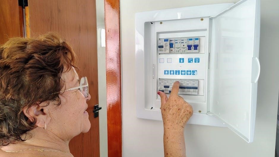
What is a Manual Transfer Switch?
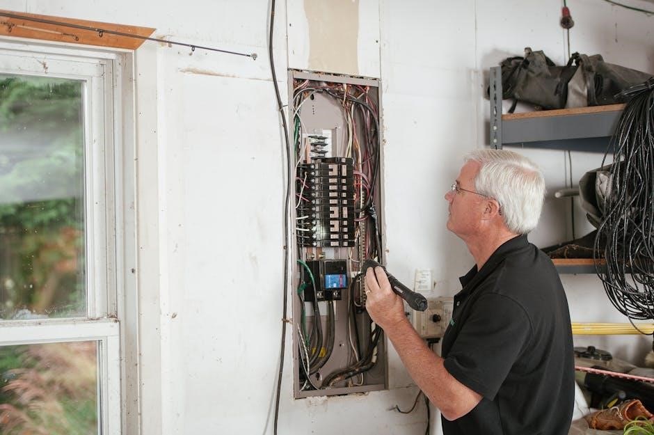
A manual transfer switch is a crucial electrical device designed to safely connect a portable generator to your home’s electrical system during a power outage. Unlike automatic transfer switches, it requires manual operation – you physically switch the power source from the utility grid to the generator.
Essentially, it acts as a gatekeeper, isolating your home from the potentially dangerous backfeed of electricity onto the utility lines, which could harm line workers. This isolation is paramount for safety and code compliance. It’s a flexible and economical solution, especially as reliance on backup power grows with increasingly severe weather events.
The switch itself contains a series of breakers, allowing you to select which circuits you want to power with the generator, optimizing its output and preventing overload. Understanding its function is the first step towards mastering your new wiring diagram.
Why Use a Manual Transfer Switch?
Employing a manual transfer switch offers significant advantages during power outages. Primarily, it provides a safe method for utilizing a generator, preventing dangerous backfeeding to the utility grid – a critical safety concern. It’s a cost-effective alternative to automatic systems, offering flexibility in powering essential circuits.
As extreme weather events become more frequent, reliable backup power is increasingly vital. A transfer switch allows you to maintain functionality for necessities like refrigerators, heating systems, and medical equipment. Mastering the wiring diagram empowers homeowners to control these functionalities with precision.
Furthermore, it avoids the need for extension cords snaking throughout your home, creating a cleaner and safer power distribution setup, especially during prolonged outages.
Understanding the Wiring Diagram Basics
Wiring diagrams are essential for safe and correct installation, illustrating connections between the main power, generator, and load center for seamless power transfer.
Key Components of a Transfer Switch System
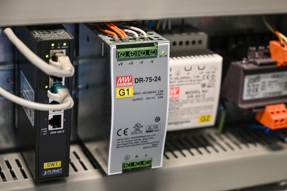
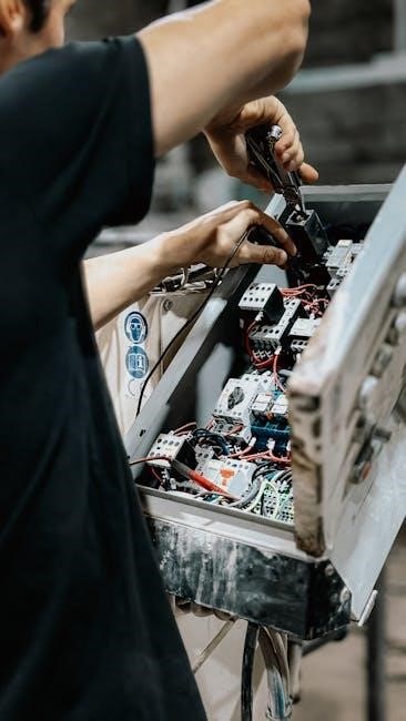
A manual transfer switch system comprises several crucial components working in harmony to deliver backup power. The transfer switch itself is central, physically routing power between sources. Main circuit breakers protect the electrical panel from overload, while generator-specific breakers safeguard the generator.
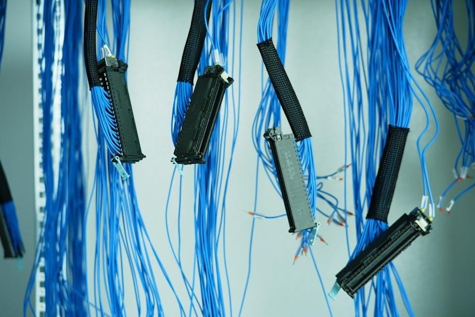
Wiring conduits ensure safe cable routing, and appropriately sized electrical cables carry the current. Neutral conductors and grounding wires are vital for safety, preventing shocks and ensuring proper operation. Understanding each component’s role, as detailed in the wiring diagram, is paramount for a successful and safe installation. Proper component selection, matching generator output to switch capacity, is also essential.
Common Wiring Symbols Used in Diagrams
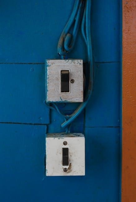
Decoding a manual transfer switch wiring diagram requires familiarity with standard electrical symbols. A straight line represents a conductor, while a breaker symbol indicates a circuit interruption device. Circles often denote connection points or junction boxes. Grounding symbols, typically resembling stacked lines, signify earth connections for safety.
Voltage and amperage ratings are frequently noted near components. Understanding these symbols is crucial for accurately interpreting the diagram and performing a safe, correct installation. Mastery of these visual cues unlocks the secrets of the system, empowering precise control and successful operation, as outlined in the user manual.
Safety Precautions Before Wiring
Prioritize safety! Always disconnect main power before wiring, utilize proper safety equipment, and ensure full compliance with local electrical codes for a secure installation.
Disconnecting Power Before Starting

Crucially, before commencing any wiring work related to your manual transfer switch, completely disconnect the main power supply to your home’s electrical panel. This is a non-negotiable safety step, preventing severe electrical shock and potential fatal injuries. Locate the main breaker, typically found within your breaker panel, and switch it to the ‘OFF’ position.
Double-check with a voltage tester to confirm that power is indeed absent at the wiring locations where you’ll be working. Never assume the power is off solely based on the breaker position; always verify with a tester. This precaution safeguards both you and your property, ensuring a safe and successful transfer switch installation. Remember, electricity is unforgiving, and caution is paramount.
Using Proper Safety Equipment
Prioritize safety by equipping yourself with the correct personal protective equipment (PPE) before beginning any manual transfer switch wiring. This includes insulated gloves rated for electrical work, safety glasses to protect your eyes from sparks or debris, and a non-conductive ladder if working at height.
Wear appropriate clothing – avoid loose garments and jewelry that could create a hazard. A face shield offers additional protection. Ensure your voltage tester is in good working order and properly rated. Having a well-stocked first-aid kit nearby is also advisable. Remember, a safe work environment minimizes risks and allows for a focused, successful installation.
Local Electrical Code Compliance
Adhering to local electrical codes is paramount when installing a manual transfer switch. Regulations vary significantly by location, dictating acceptable wiring methods, grounding requirements, and permissible switch types. Contact your local building department to obtain the necessary permits and understand specific code requirements before starting any work.
Failure to comply can result in fines, safety hazards, and voided insurance coverage. Ensure the transfer switch is appropriately sized for your generator and electrical panel. A qualified electrician can provide invaluable guidance, ensuring your installation meets all applicable standards and operates safely and legally.
Step-by-Step Wiring Guide
Carefully follow a detailed wiring diagram, connecting the main power, generator, and load center sequentially, ensuring secure connections and proper breaker alignment for safety.
Connecting the Main Power Line
Begin by identifying the main power line entering your home’s electrical panel – typically, this consists of two or three hot wires, a neutral, and a ground. Crucially, ensure the main breaker is completely switched OFF before proceeding; safety is paramount. Connect these wires to the corresponding terminals on the manual transfer switch, meticulously matching the phases and polarity as indicated in your specific wiring diagram.
Use appropriately sized wire connectors and tighten them securely to prevent loose connections, which can cause arcing or overheating. Double-check all connections against the diagram before moving forward, verifying that each wire is firmly seated and correctly positioned. Proper labeling of wires during this stage can also be incredibly helpful for future maintenance or troubleshooting.
Connecting the Generator Power Line
After safely shutting down the generator, connect its power output to the designated terminals on the transfer switch. Similar to the main power line, this involves matching hot wires, neutral, and ground, strictly adhering to your wiring diagram’s specifications. Employ appropriately sized wiring and secure connectors to ensure a robust and reliable connection, preventing potential hazards.
Verify correct polarity before tightening connections; reversed polarity can damage appliances. It’s essential to ground the generator properly to the transfer switch’s grounding terminal, safeguarding against electrical shock. Double-check all connections for tightness and accuracy, referencing the diagram frequently.
Wiring the Load Center (Breaker Panel)
This step connects the transfer switch to specific circuits within your breaker panel, enabling selective power restoration during outages. Identify the circuits you intend to power with the generator – typically essential loads like refrigerators, lights, and heating systems. Wire each selected circuit’s hot wire to the corresponding terminal on the transfer switch, following the diagram meticulously.
Ensure proper wire gauge compatibility and secure connections. The neutral wires from these circuits remain connected to the main breaker panel’s neutral bus. Never backfeed power into the main panel; the transfer switch isolates the generator power.
Different Types of Manual Transfer Switch Configurations
Transfer switches vary by the number of circuits they support – commonly 6, 8, or 10 – impacting the extent of backup power available during outages.
6-Circuit Transfer Switch Wiring
A 6-circuit manual transfer switch is a popular choice for backing up essential household loads. Wiring involves connecting the main power line from your utility, and the generator power line, to the switch’s designated terminals.
Each of the six circuits then connects to specific breakers within your load center (breaker panel). Careful labeling is crucial to identify which appliances or circuits will receive power during an outage.
Typically, these circuits include vital systems like refrigerators, sump pumps, furnaces, and lighting. Proper grounding is essential for safety, and adherence to local electrical codes is paramount throughout the wiring process. Diagrams are vital for correct connections.
8-Circuit Transfer Switch Wiring
An 8-circuit manual transfer switch expands backup power capabilities, allowing for more essential circuits to operate during outages. The wiring process mirrors that of a 6-circuit switch, beginning with connecting the main power feed and generator input to the designated terminals.
However, with two additional circuits, careful planning is needed to prioritize critical loads. Common choices include adding a well pump, additional lighting, or a dedicated freezer circuit.
Accurate labeling of breakers within the load center is even more vital. Always ensure proper grounding and strict adherence to local electrical codes for a safe and functional installation, referencing detailed wiring diagrams.
10-Circuit Transfer Switch Wiring
A 10-circuit manual transfer switch provides substantial backup power, accommodating nearly all essential household circuits during prolonged outages. Wiring involves connecting the main power line and generator feed to the switch, similar to smaller configurations, but demands meticulous organization.
Prioritization of circuits becomes paramount; consider essential appliances, heating systems, and critical medical equipment. Clear labeling of breakers within the load center is absolutely crucial for easy identification and safe operation.
Double-check all connections against a verified wiring diagram, ensuring proper grounding and adherence to local electrical codes. This configuration offers robust protection, but requires careful planning and execution.

Troubleshooting Common Wiring Issues
Addressing wiring problems requires systematic checks for power transfer, tripped breakers, and voltage accuracy, ensuring safe and effective generator operation during outages.
No Power Transferring
If power isn’t transferring from the generator to your home, begin with a thorough inspection of the transfer switch itself. Verify the switch is correctly positioned to the “generator” setting, and confirm all wiring connections are secure – both at the switch and within the load center.
Check the generator’s output; ensure it’s producing the correct voltage and amperage. A tripped breaker on the generator or within your main panel can also halt power flow. Inspect all breakers associated with the transfer switch circuit, resetting any that have tripped.
Double-check the wiring diagram to confirm proper connections, paying close attention to neutral and ground wires. A loose connection or incorrect wiring can prevent power transfer. Finally, verify the main breaker is off before attempting to backfeed power.
Breakers Tripping Frequently
Frequent breaker tripping indicates an overload on the circuit connected to the transfer switch. Reduce the load by disconnecting some appliances or devices powered through the switch. Ensure the generator’s wattage capacity isn’t being exceeded; running too many high-demand appliances simultaneously can cause this issue.
Inspect the wiring for any signs of damage, loose connections, or improper gauge wire. Undersized wiring can overheat and trip breakers. A faulty transfer switch itself could also be the culprit, requiring professional inspection.
Verify that the breakers are appropriately sized for the circuits they protect. If tripping persists, consult a qualified electrician to diagnose and resolve the underlying problem, ensuring safe operation.
Incorrect Voltage Readings
Inconsistent or incorrect voltage readings from the generator or at the transfer switch suggest a problem with the generator’s output or the wiring connections. First, verify the generator is producing the correct voltage – typically 120/240V in North America – using a multimeter.
Check all wiring connections between the generator, transfer switch, and load center for tightness and corrosion. Loose connections can cause voltage drops. Ensure the transfer switch is correctly configured for the generator’s output.
If the generator’s voltage is correct but readings at the switch are off, a faulty transfer switch component may be the cause; professional diagnosis is recommended for safe and accurate resolution.
Generator Compatibility and Considerations
Matching generator output to the transfer switch’s capacity is essential for safe operation, alongside proper grounding techniques, ensuring reliable backup power during outages.
Matching Generator Output to Switch Capacity
Ensuring compatibility between your generator’s power output (measured in watts) and the transfer switch’s rating is paramount for safe and effective operation. The switch must handle the total wattage of the circuits you intend to power during an outage.
Carefully calculate the wattage requirements of essential appliances and devices – refrigerators, lights, sump pumps – and select a generator that comfortably exceeds this total.
Undersizing the generator can lead to overloading and potential damage to both the generator and the switch, while significantly oversizing is inefficient and costly. Always consult the transfer switch’s specifications and the generator’s manual to verify compatibility before installation, prioritizing safety and optimal performance.
Proper Generator Grounding
Effective grounding is a critical safety measure when integrating a generator with a manual transfer switch system. It prevents electrical shock and protects equipment from damage by providing a path for fault currents to safely dissipate into the earth.
Always connect the generator’s grounding terminal to a dedicated grounding rod driven into the earth, following local electrical code requirements. Never rely on the neutral wire for grounding, as this can create a hazardous situation.
Proper grounding ensures the transfer switch operates safely and reliably, safeguarding your home and family during power outages. Consult a qualified electrician if you are unsure about proper grounding techniques.
Advanced Wiring Techniques
Interlocking kits and conduit offer enhanced safety and wire protection during manual transfer switch wiring, improving system reliability and longevity;
Interlocking Kits for Enhanced Safety
Interlocking kits represent a significant upgrade to standard manual transfer switch wiring, providing an extra layer of protection against a potentially hazardous situation: backfeeding power onto the utility grid. These kits physically prevent the main breaker and the generator breaker from being engaged simultaneously.
This mechanical interlock is crucial because it eliminates the risk of sending electricity back through the power lines, which could endanger line workers and damage equipment. Installation typically involves replacing the existing main breaker with a special interlocking breaker, or adding a separate interlocking device.
Proper installation, adhering to local electrical codes, is paramount. While offering increased safety, interlocking kits don’t replace the need for careful wiring and adherence to all safety precautions during the transfer switch installation process.
Using Conduit for Wire Protection
Electrical conduit plays a vital role in safeguarding the wiring associated with a manual transfer switch installation, enhancing both safety and longevity. Conduit, typically made of metal or plastic, encases the wires, shielding them from physical damage, moisture, and potential corrosion.
Its use is often mandated by local electrical codes, particularly for exposed wiring runs or in areas prone to physical impact. Properly installed conduit provides a grounded pathway, further reducing the risk of electrical shock and improving system reliability.
Selecting the appropriate type and size of conduit is crucial, ensuring it meets code requirements and adequately accommodates the wiring. Careful attention to conduit bends and connections is essential for a secure and compliant installation.
Resources and Further Information
Explore online databases for wiring diagrams and consult a professional electrician for personalized guidance, ensuring a safe and compliant manual transfer switch setup.
Online Wiring Diagram Databases
Numerous online resources offer a wealth of manual transfer switch wiring diagrams, catering to various configurations like 6, 8, and 10-circuit systems. These databases frequently include schematics from reputable manufacturers, providing detailed visual guides for DIY enthusiasts and professionals alike.
Websites dedicated to electrical engineering and home improvement often host user-submitted diagrams and troubleshooting guides, fostering a collaborative learning environment. However, always verify the accuracy of information sourced from these platforms, cross-referencing with official documentation whenever possible.
Manufacturer websites are invaluable, often providing specific diagrams tailored to their products, alongside user manuals detailing operation and safety precautions. Remember to prioritize safety and consult a qualified electrician if you encounter any uncertainties during the wiring process.
Professional Electrician Consultation
Engaging a qualified electrician is paramount when dealing with manual transfer switch wiring, ensuring safety and code compliance. While online resources offer diagrams, a professional brings expertise in interpreting them correctly for your specific setup.
Electricians can assess your electrical panel, generator capacity, and local regulations to recommend the optimal transfer switch configuration. They’ll handle the complex wiring, grounding, and breaker connections, minimizing risks of electrical hazards or damage.
Furthermore, a professional inspection guarantees the system functions flawlessly during power outages, providing peace of mind. Don’t hesitate to seek their guidance – it’s a crucial investment in your home’s safety and reliable backup power.